|
|
english
version 
|
|
T3 Spy/Assault - Vehicle
by
Randy Coolbaugh
|
!!
Please note, that loading times may be increased due to
the picture sizes !!
!!
Picture sizes shown, when "hovering" !!
|
|
|
| |
|
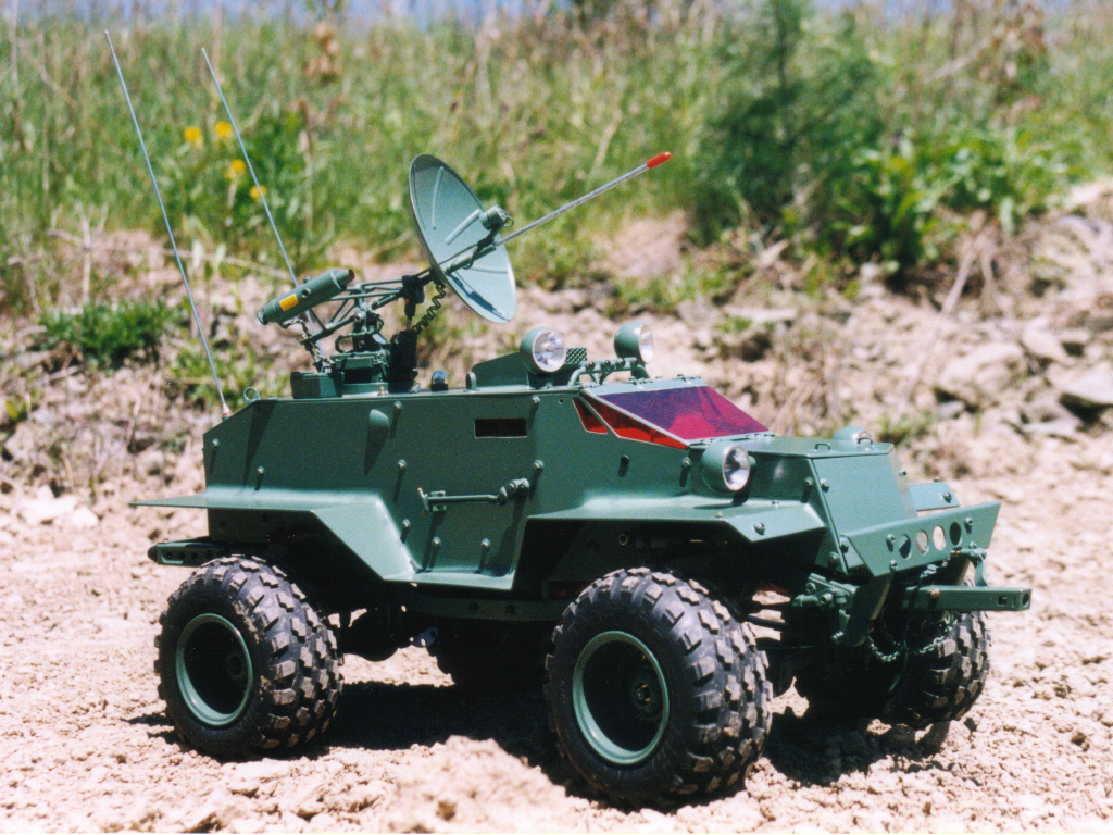
"Once
upon a time...", the story of this outrageous vehicle
could have started like this. In January 1996 an article has
been published in the Radio Control Car Action Magazine (RCCA),
in which Randy introduced his "Terminator 3" to
the bedazzled readership. The RCCA asked their readers at
that time: "ARE YOU READY for something a little different?
How 'bout a whole lot different?", and did not
exaggerate. Randy has put one of the most unconventional,
but well-devised, creations on its wheels. Blueprints go back
to the year of 1989. Randy wanted to build a fully functional,
scale, Spy/Assault-Vehicle, that could be controlled without
visual contact between car and driver. He wanted to incorporate
such ambitious features like a working flamethrower and rocketlauncher,
proximity alert and a pinpoint listening device in this model.
After one month of planning Randy had completed a really promising
sketch, and he was determined to realize it. All that was
missing was a suitable chassis, capable to carry his construction.
Randy soon came to the decision that the Bruiser was the right
chassis, but he couldn't find one at that time. A Cousin finally
ceded his Bruiser to him.
|
| |
 |
|
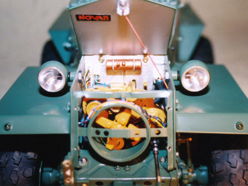
T3 started from a heavily modified bruiser chassis. First,
the stock motor was fitted with a copper cooling coil, with
a belt driven two-gear coolant pump. The heated coolant is
pumped to an aluminum radiator with a thermostatically controlled
electric fan; also on the motor there is a built driven fan
and a functioning alternator.
The
stock and very stiff slipper clutch was replaced with an altered
team losi hydra drive fluid torque converter.
|
| |
|
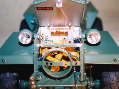
Left
picture: The motor compartment of the T3. Clearly visible
the motor fan, some secondary units and the mounted RAM-Lights
|
|
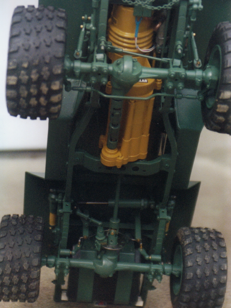
The
rear axle was equipped with an electrically actuated disk
brake on the drive shaft yoke and a scratch built differential.
This is the weakest point in the drive chain. I had to use
very small gears in order to fit the unit inside the stock
axle housing. Both axles had additional leaves added, for
8 in the rear and 5 in front, torque arms, and pan hard links
and centi-lever shock system.
The
tires and rims had to be sealed and small valves were installed
to hold air pressure, T-3 is fully ball bearing and weighs
in at 30 pounds.
|
|
The
body was designed crossing features of a HMMWV and a German
half-track called GREIF. The body assembly is divided into
4 compartments, each separated by a 1/8" bulkhead.
The
first compartment (under the glass) is the cockpit, housing
all the switches, variable resistors, LED indicators, and
the video camera and audio microphone. Under the console is
the steering and shifting servos.
The
second compartment holds the electronics. This would be identified
by the small rectangular windows. Most of which have been
reconstructed on integrated circuit boards. These consist
of two four channel receivers, signal monitor, battery monitor,
temperature sensor, light sensor, the onboard systems monitoring
and warning circuits, and on top is the e.s.c. and radiator
topped by an electric fan.
The
third compartment (under the turret) holds the mechanical
workings. Servos, for the turret, hydraulic master cylinder
for the snowplow, rotor switch for the armament firing and
flame thrower fuel pump and tank.
|
|
|
| |
|
Right
picture: The bottom of the T3 with the impressing chassis.
Note the motor with cooling coil, the sophisticated suspension
and the disc brake on the rear drive shaft.
For
an enlarged view click on the picture.
|
|
The
rear compartment holds the a/v transmitter, relay board, tilt
sensor, and on the outside the proximity sensor.
The
turret has a rise of 8 degrees and a rotation of 90 degrees;
it has a class 3A-laser sight. It can launch single estes
A-3 rockets, or slide on a MRLS unit, and shoot "bottle"
rockets. This unit was damaged last fall during testing when
a rocket failed to launch and detonated in the tube. There
is also a 4-inch parabolic microphone that attaches to the
turret for pinpoint listening.
This
truck is capable of being operated without visual contact
with a range of up to 2000 feet. In stealth mode (no lights)
you can see up to 8 feet in total darkness with infrared.
All the monitoring circuits, battery, tilt, proximity, and
signal are connected via optic links to a pizzo driver circuit
which sends different audio tones back to the control unit
to help identify possible problems.
|
 |
|
In
the event of signal loss the monitoring circuit puts the transmission
in neutral thus any RX interference cannot bring harm. Also,
the system transmits a warning tone and activates a roof mounted
locator beacon.
If
you remember the article in RCCA January 1996 this was the
T-3 before a small electrical fire. The new T-3 still has
all the same features but with a few improvements and body
alterations. Randy has yet to build the control unit; he is
having too much fun tinkering with the truck.
|
| |
|
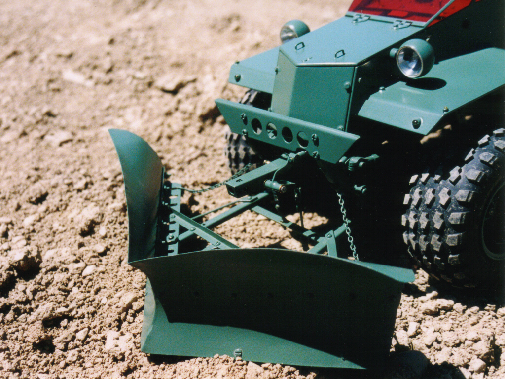
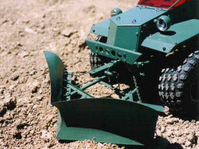
Left
picture: The T3 with mounted Plow, which can be moved hydraulically.
For
an enlarged view click on the picture..
|
| |
| |
|
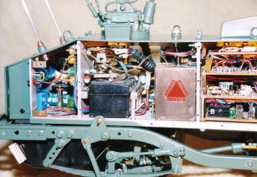
Right
picture: The rear end of the T3 w/o sheetmetal. The
truck is nearly bursting with all that electronics inside.
A electrical layout plan for all this must drive an
electrical engineer nuts.
|
|
 |
| |
 |
|
| Technical
data : |
|
Length:
|
23.0
|
in.
|
|
| Width: |
9.0
|
in.
|
|
| Height: |
11.0
|
in.
|
|
| Wheelbase: |
11.5
|
in.
|
|
| Tread
f/r: |
7.75/9.0
|
in.
|
|
| TyreØ |
4.0
|
in.
|
|
| Tyrewidth |
2.0
|
in.
|
|
| Weight |
29
|
lbs.
|
|
|
|
|
|
|
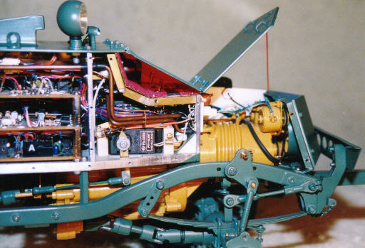
Left
picture: The front half of the T3 w/o "armament".
The impression of the built-in technique is coming
to completion. Cleary visible the motor-tranny-unit
with the secondary units.
|
|
|
| |
|
All
pictures are under the copyright of Randy Coolbaugh, NY, USA
|
|
|